X-Band Doppler Radar Speed Gun
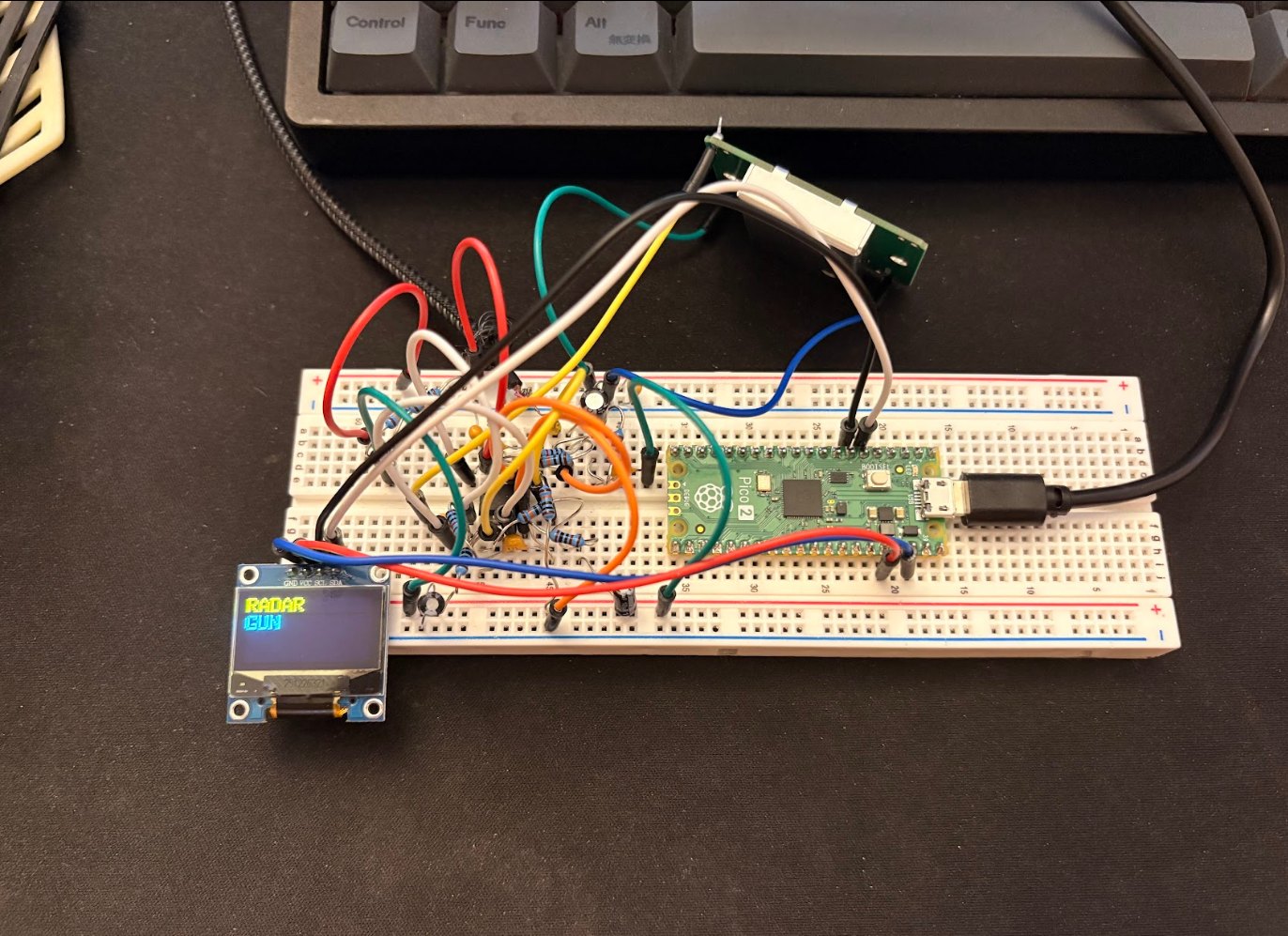
A fully self-contained, handheld radar speed gun that measures vehicle speed in real time, from a 10.525 GHz X-band module, through a custom analog signal-conditioning chain, into a real-time 1024-point FFT pipeline, and onto an embedded microcontroller driving a live OLED readout. It runs standalone on a USB power bank, no computer required. One signal, carried all the way from physics to a number on a screen.
End-to-end, multi-domain, solo
Most student projects live in one domain, just embedded, or just a circuit. This one crosses RF → analog → DSP → embedded → UI, built and debugged solo from physics first principles to a working physical device. Each subsystem was validated independently before integration, mirroring real product development, and the result is a tangible, demonstrable instrument with measurable accuracy, not a simulation.
From Doppler shift to speed
A moving object reflects the radar's wave back at a slightly shifted frequency, higher when approaching, lower when receding. That shift is directly proportional to speed, so measuring it gives the velocity. At X-band, the math works out to a clean constant:
Illustration of the Doppler return, wavefronts compress as a source approaches the sensor and stretch as it recedes.
Key specs
Conditioning a µV signal
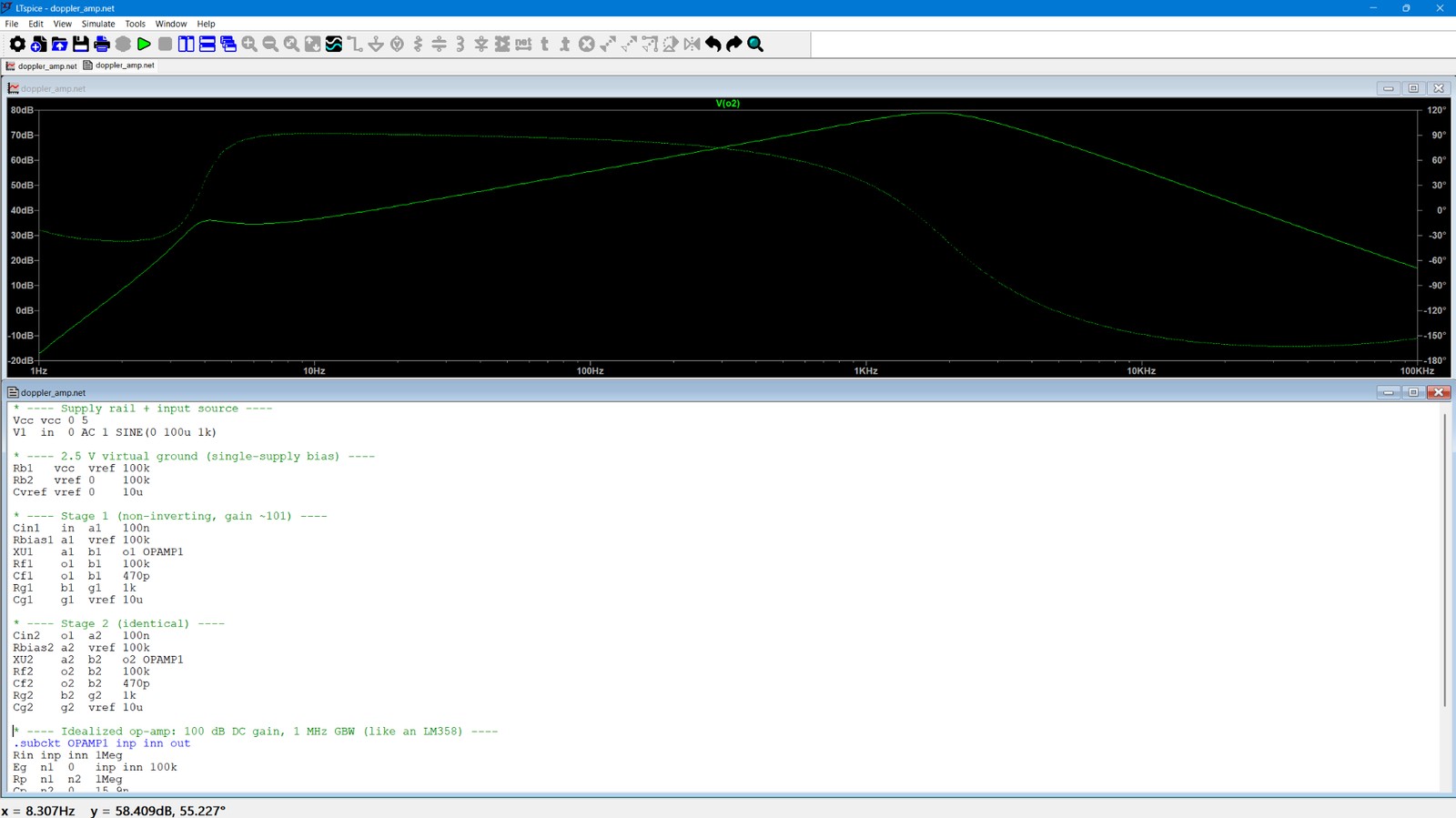
The HB100's baseband output is tiny, microvolts to millivolts. A multi-stage amplifier boosts it to usable ADC levels, with 100 nF AC coupling to strip DC offset and a 10 kΩ / 10 kΩ divider to 3.3 V biasing the AC signal for single-supply sampling. I verified the whole amplifier in LTspice before building, a two-stage non-inverting design (~101× per stage) around an LM358-class op-amp model, then prototyped and debugged it on a breadboard.
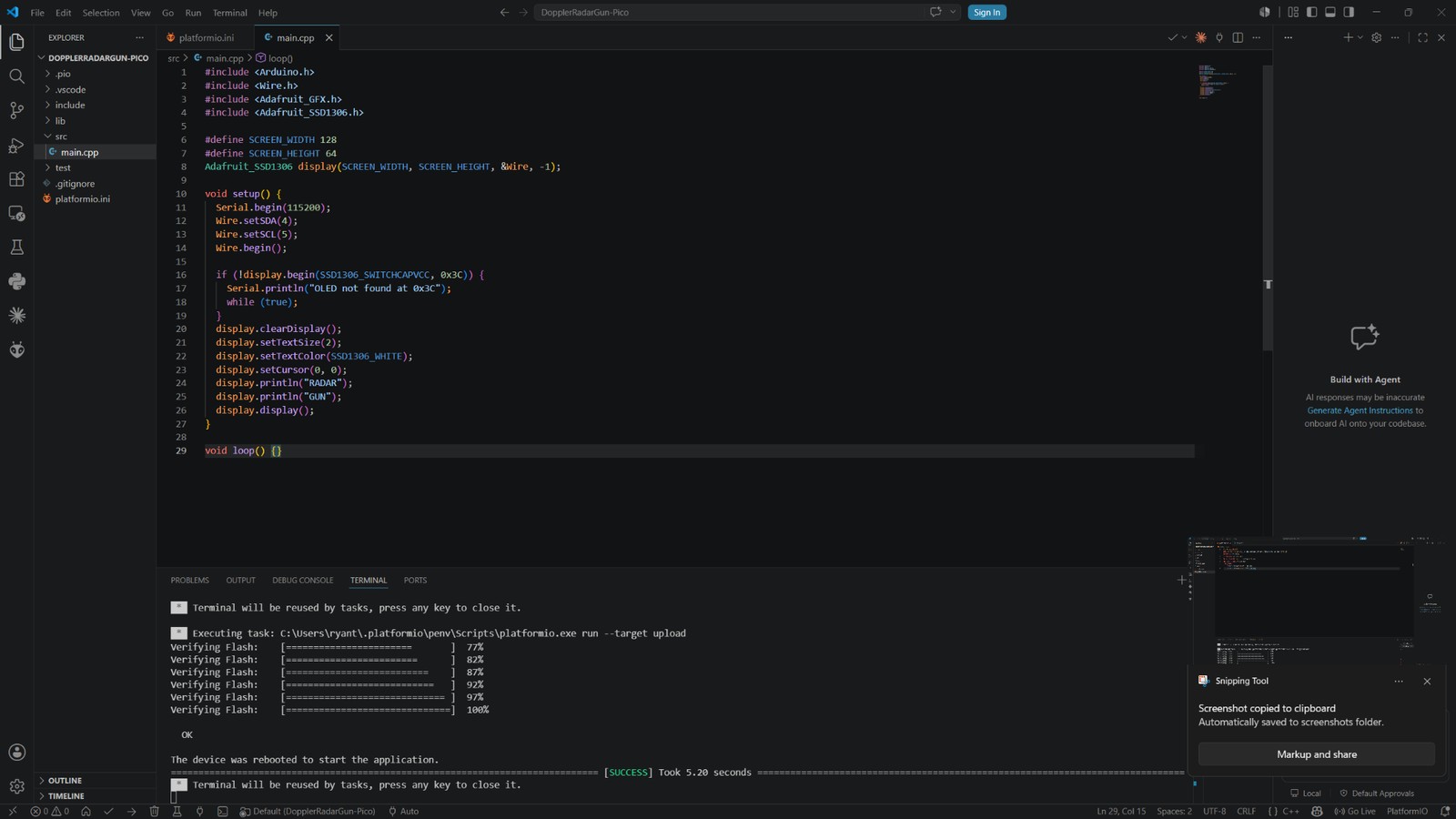
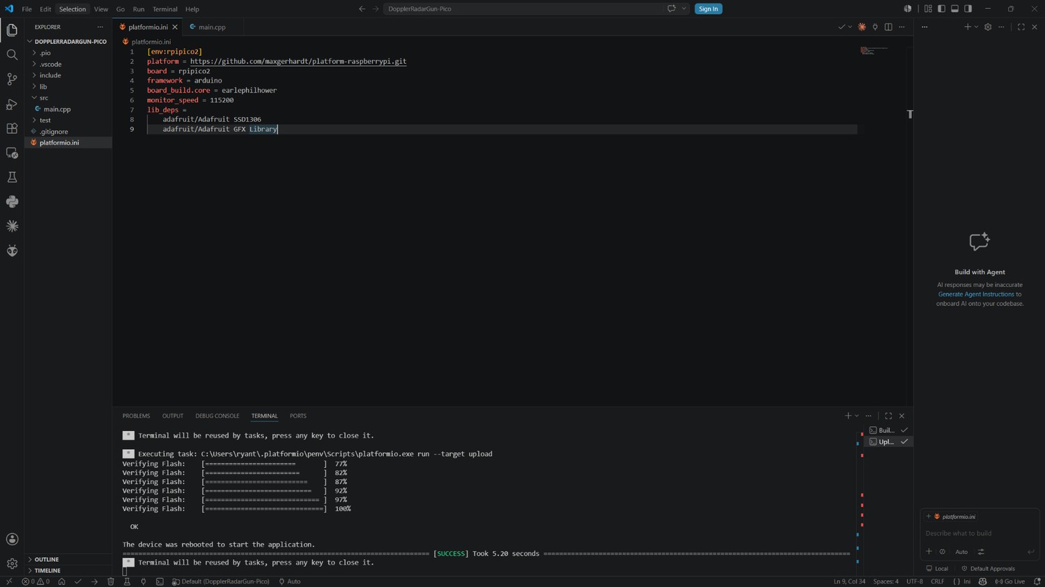
A phased build
From simulation to silicon
Tap any image to enlarge.
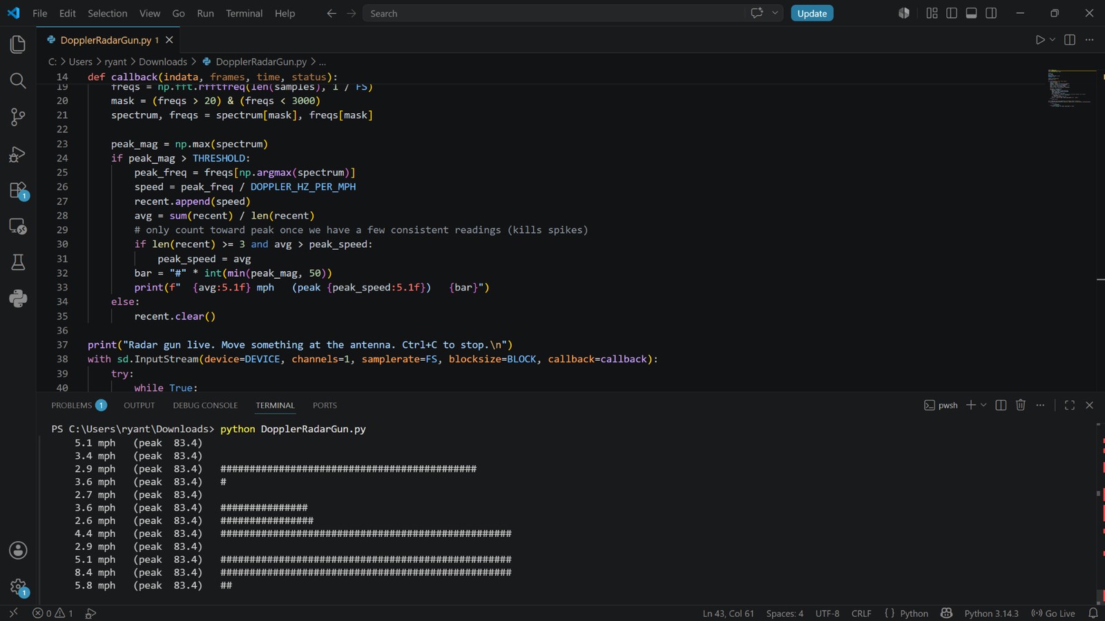
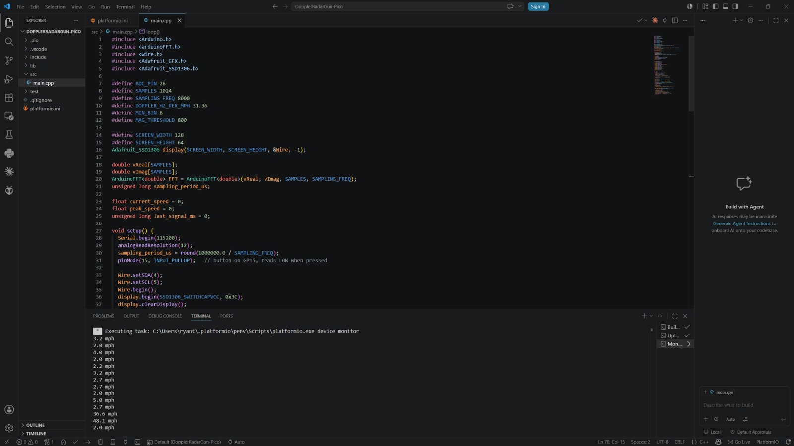
Demos & bench tests
Bench tests and demos, embedded below. If a clip doesn't load, set its Google Drive sharing to “anyone with the link.”
Debugging discipline
Debugged the full chain stage by stage, power-rail verification, continuity testing, and signal tracing, and used Audacity to capture and analyze the conditioned signal during bring-up, isolating components to get true in-circuit readings.
What's next
Porting the DSP into custom digital logic on an FPGA (Tang Nano 9K), moving the signal processing from software into hardware, toward hardware-level DSP and digital design.